How Reverb Works
The acoustical effect of REVERBERATION can be thought of as the complex interactions of delayed sound. It can be heard in nearly any listening environment, taking place when sound waves traveling through the air are reflected by surfaces such as walls, ceilings, and floors.
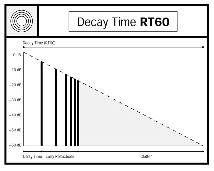
The properties of reverberant sound are most noticeable in the case of a single abrupt sound impulse, such as a hand clap or a door being slammed in a large room. At first, it is possible for the ear to hear individual echoes, referred to as EARLY REFLECTIONS. The time between the initial sound taking place and the arrival of a reflection of this sound is referred to as the DELAY TIME. These initial delays give the listener a sense of the overall size of the listening space.
After the delayed impulses have traveled back and forth through the listening space several times, the individual delayed sounds increasingly overlap one another. This blending of echoes into a random breath-like effect is called CLUTTER, and gives the listener a sense of the the acoustical reflective quality, or 'liveliness,' of the listening environment.
The combined length of these phases is called the DECAY TIME. The standard used in architectural acoustics is the time required for the overall reverberant sound to decay to a measured value of 60 decibels below the level of the original "dry" sound. This term is often abbreviated as RT60.

Throughout the history of audio amplification, numerous techniques have been developed to simulate the natural effect of reverberation. These have included acoustic chambers and pipes (reflective spaces into which a speaker and microphone were placed), large steel plates (the Gotham Audio EMT series), and recirculating delay mechanisms based on magnetic tape (the Maestro "Echo-Plex"), or rotating electrostatic elements (the Tel-Ray "Organ Tone," later licensed to Fender Musical Instruments). Developments in solid-state electronics yielded the analog 'bucket brigade' (capacitive charge-coupled) delay, and most recently, digital delay technology.
The use of coiled springs to delay audio signals was originated by early telecommunications engineers to simulate the effects of long-distance telephone lines. While the prolonged sequence of echoes was undesirable for their purposes, it seemed most useful to an inventor named Laurens Hammond, who promptly appropriated the concept for use with the keyboard instrument which bears his name.
The coiled spring mechanisms underwent a continuing process of refinement. In the early 1960's, a Hammond engineer named Alan C. Young developed a design which proved to be practical for portable use. Since then Spring Reverb has found its way into applications ranging from High Fidelity audio to car radios.
Spring Reverberation units use a combination of electromagnetic and mechanical elements to simulate paths of delayed sound. an audio signal drives the COIL of the INPUT TRANSDUCER, which applies a twisting force to miniature cylindrical MAGNETS attached to a set of precision stainless steel TRANSMISSION SPRINGS. The twisting motion travels as a wave impulse down the length of the springs until it is rebounded by the OUTPUT TRANSDUCER, which also uses magnetic components to generate a delayed output signal.
In addition to the coil and magnets, the transducers also contain DAMPER DISCS within the BRASS SLEEVE assemblies. The SUPPORT WIRES, to which the magnets are mounted, pass through the discs, which results in a controlled application of friction, or 'braking' action, on the twisting spring assemblies. The DECAY TIME performance specification of a reverb unit is dependent on the choice of material type and thickness of the DAMPER DISC; the TRANSMISSION SPRINGS are the same for all the available decay time ranges for any given model.
If the input of a single-spring reverb assembly was driven with a single pulse-like signal (an amplified 'snap'), a series of delayed output pulses would result. The first delay would represent the amount of time the sound required to travel through an equivalent of the uncoiled length of the spring. Following this, the pulse would be reflected from the output side, travel back through the spring, be reflected by the input side, and return through to the output side. This results in subsequent delays having a length of twice the initial DELAY TIME.
When the spring is driven with a sustained audio signal, the delayed reflections overlap the incoming sound. Depending upon the frequencies found in the incoming signal, the reflected sound can interact to result in a series of RESONANCES.
To avoid this unevenness over the frequency response range in an actual reverb unit, two or three spring delay paths are used, each with a different delay time rating. The Type 4 (full-sized two-spring) reverb unit, for example, provides DELAY TIMES of 34 and 41 milliseconds, chosen for the fullest and most even overlapping of delayed sound.